
There are a lot of varieties of electric motor categorized by structure and signal type, motors convert electrical energy into mechanical energy using electromagnetic principles. The energy conversion method is fundamentally the same in all electric motors.
Motor operation is based on the attraction and repulsion between magnetic poles. An three-phase motor shown in below, the process starts when current flows through one of the three stator windings and generates a magnetic pole that attracts the closest permanent of the opposite pole, the rotor will move if the current shifts to an adjacent winding. Sequentially charging each winding will cause the rotor to follow in a rotating field.
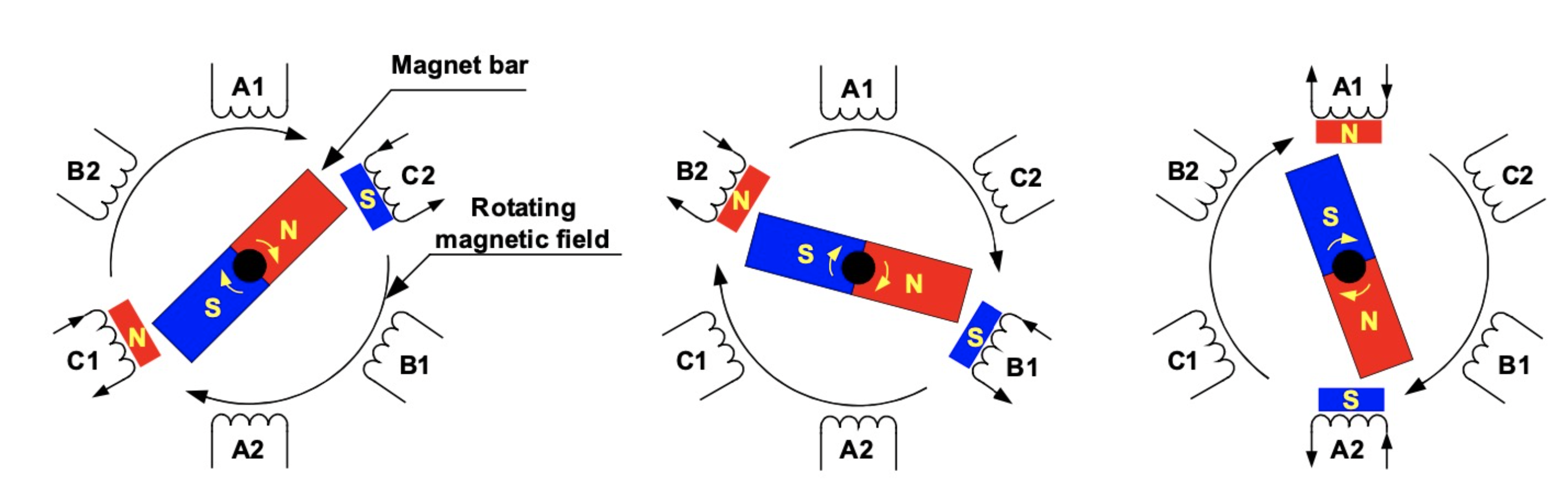
Figure 1-Motor Rotation Theory
Permanent Magnet (PM) motor accomplishes commutation electronically using the rotor position feedback to determine when to switch the current, feedback process goes through a Hall sensor or senseless rotatory encoder. The stator windings work in conjunction with permanent magnets on the rotor generate a nearly uniform flux density in the air gap. This permits the stator coils to be driven by a constant DC voltage, rotor permanent magnetic field and stator electromagnetic field are running at the same frequency, synchronous motor operation. Whereas in an Induction Motor (ACIM), it requires a sinusoidal AC current to flow through the stator to create a rotating variable magnetic field that induces a current in the rotor (winding structure with non-ferrous material). This induced current circulates bars of the rotor to generate a magnetic field. It appears frequency difference between these two electromagnetic fields in asynchronous motor operation.
Obviously PM motor is a synchronous motor, while ACIM motor is an asynchronous motor, where rotor runs at a lower frequency than stator by slip frequency and slip increases with load on the motor. ACIM motor performs nonlinear characteristic of lower torque at lower speeds, but PM motor presents higher starting torque at low speed with very fast dynamic response due to the rotor position feedback function.
IPM stands for Interior Permanent Magnet motor. It is a type of electric motor that combines the features of both Permanent Magnet (PM) motors and Induction motors. Rotor magnet position can significantly alter the electrical properties of a PMSM, mounting the rotor magnets on the surface -as shown in Figure 2(a)-results in lower torque ripple, while burying the magnets inside the rotor structure-as shown in Figure 2(b) increases saliency, which increases the reluctance torque of the motor.In an IPM motor, permanent magnets are embedded in the rotor, creating a magnetic field. IPM rotor interacts with the stator windings, which are supplied with alternating current (AC). The interaction between the magnetic field of the rotor and the rotating magnetic field of the stator induces a torque, causing the motor to rotate.
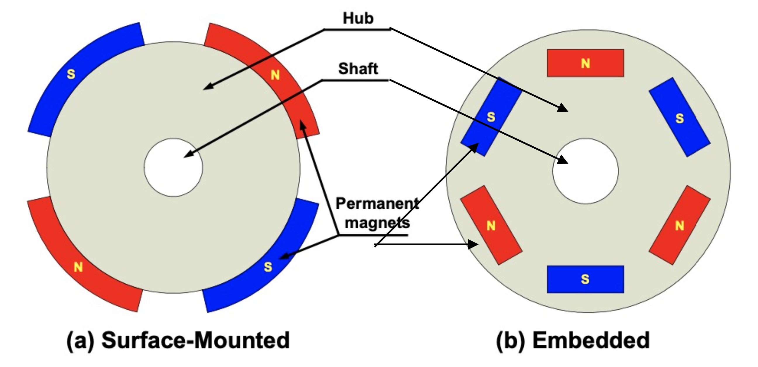
Figure 2-Magnet Surface-Mounted and Embedded Rotor
There are multiple IMP Motor Rotor magnet structures, including loaft magnet, flat magnet single layer or multi-layer, V form rotor magnet distribution, double V form rotor magnet distribution, etc., various rotor magnet structures or distributions performs different characteristics for different application purposes.
Loaft magnet in IPM motor rotor, makes air gap magnetic flux waveform to be more sine, it is beneficial in electrical vehicle motors for optimizing NVH.
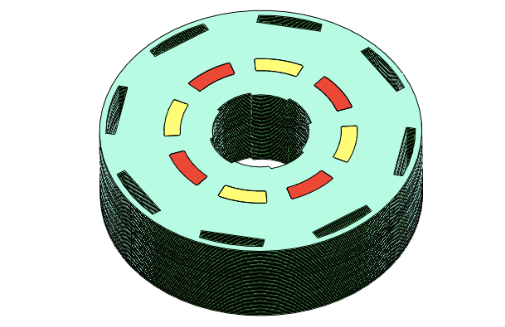
Figure 3- Loaft Magnet Rotor
Flat magnet of IPM rotor, combines the slender holes around the rotor steel slots, intending to optimize the air gap magnetic flux waveform, of course, more permanent magnets in multiple layers, more costly.
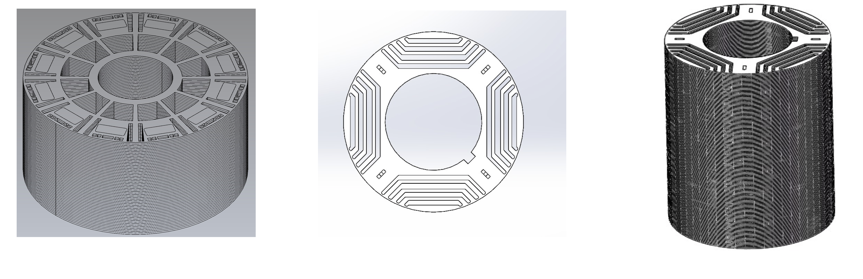
Figure 4- Single layer and Multi-layer Flat Magnet Rotor
V form rotor magnet distribution, is ruching the flexibility designation, no insulation bridge between 2 magnets, but dividing bridge designation can boost the RPM from 6,000RPM to 13,500 RPM. Typically Tesla has been using V rotor magnets with dividing bridge, an excellent combination of magnetic poles and slots, less poles than normal electrical motor, making motor run at the same RPM but lower frequency, more friendly to control, particularly lessening the performance stress at higher RPM. Optimal V form rotor magnet distribution by replacing 1 dividing bridge with 2 downsized dividing bridges, reducing magnetic flux leakage and improving motor performance with motor robust rotor configuration. Another optimized V form rotor magnet distribution, more flexible to optimize magnetic field, higher efficiency of using magnetic energy and output better motor performance.
Double V rotor magnet distribution, has been getting the trendy rotor magnet configuration driven by the demanding motor performance and EV NVH. Double V configuration is composed of 2 pairs of V formed magnets, larger ones are much bigger than smaller ones. Large V magnets are mainly for outputting power and torque, but also adjust the air gap magnetic flux waveform to be more sine, for NVH optimization. Lucid driven motor is applying the double V rotor magnet distribution.
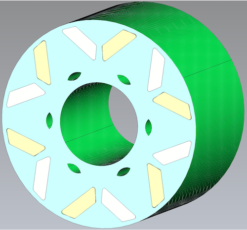
Figure 5- V Form Magnet Rotor
Rotor shape optimization is targeting to different goals, such as output torque optimization, torque ripple reduction and mechanical considerations of size limit or inertia factor. There is always a tradeoff between ripple reduction and nominal torque. Besides optimizing the rotor magnet shape of configuration, it is also feasible to optimize the Rotor by optimizing the magnet material, rotor core material, core flux barriers and Rotor size ratio.
Contact Quadrant for more about motor design.