
Linear Resonant Actuators (LRAs) are specialized vibrating motors widely used in consumer electronic devices such as smartphones, fitness trackers, and other wearables to provide haptic feedback to users. LRAs operate most efficiently when driven at their resonant frequency, typically between 100–250 Hz, which aligns with human tactile sensitivity. A sample WL 1040 LRA is shown in Figure 1.
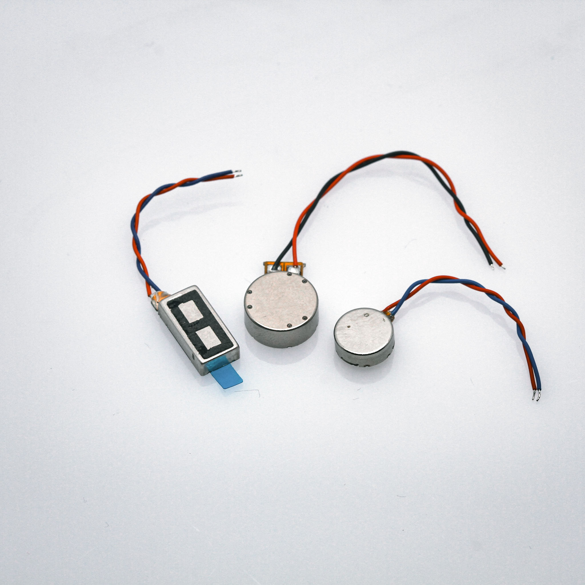
Figure 1: WL 1040 LRA.
LRAs create vibrations through the linear movement of an internal magnetic mass attached to a spring system. A system schematic is shown in Figure 2. The basic structure of an LRA includes a movable mass (typically containing permanent magnet material such as neodymium), a coil, a spring, a damper, and a housing. When electric current passes through the coil, it creates an electromagnetic field that interacts with the permanent magnet’s field. This interaction generates forces that can be either attractive or repulsive, causing the mass to move. The spring and damper connect the mass to the chassis and provide restoring forces.
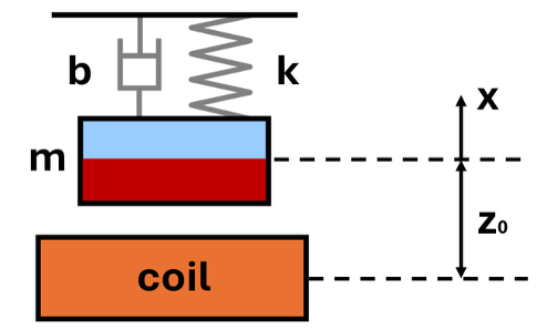
Figure 2: Schematic of the LRA with spring, mass, damper, and coil.
The movement of the mass can be modeled as a spring-damper system driven by a coil. The equation of motion can be expressed as:
mẍ + bẋ + kx = F (1)
where m is the moving mass, b is the damping coefficient, k is the spring constant, and F is the driving force from the coil. z₀ is the offset distance between the coil center and the magnet center. From this equation, the resonant frequency (in Hz) of the system can be found as:
f₀ = (1 / 2π) √(k/m)
The magnet can be modeled as a magnetic dipole moment, whose value is:
τ = -τk̂
The magnetic field of the coil along the center line is:
B = (-μ₀ N I a²) / [2(a² + z²)^(3/2)] k̂
where μ₀ is the permeability of free space, N is the number of turns, a is the radius of the coil, I is the coil current, and z is the vertical distance from the coil center. The force can then be found as the gradient of τ and B:
F = ∇(τB) = (3/2) τμ₀ N a² (a² + z²)^(-5/2) zI
In practice, the vibration displacement z changes very little. Therefore, the force can be expressed as a function of current:
F = Kₑₘ I (2)
where Kₑₘ = (3/2) τμ₀ N a² (a² + z²)^(-5/2) z and remains constant.
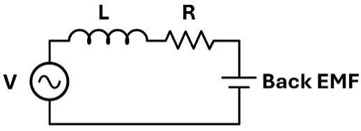
Figure 3: Schematic of the coil circuit.
A schematic of the coil circuit is shown in Figure 3. L is the coil inductance and R is the coil resistance. The driving voltage is V, and the back EMF from the moving magnet is ϵ_bemf. The circuit can be modeled as:
IR + LĪ + ϵ_bemf = V
The back EMF is induced by the movement of the magnet and can be expressed using Faraday’s Law as:
ϵ_bemf = -N dϕ/dt = -Nπa² (dB/dx) (dx/dt)
Similar to the force, the term -Nπa² (dB/dx) remains constant since the mass displacement is small. K_bemf is used to represent its value. The circuit equation then becomes:
IR + LĪ + K_bemfẋ = V (3)
Using equations (1), (2), and (3), the system dynamics of current, displacement, and acceleration can be determined under varying voltage inputs. Although the linear model cannot account for changes in spring stiffness, displacement variation, or the actual distribution of magnetic flux density, it serves as a useful tool for designing and understanding LRA systems.
The vibration of a sample WL 1040 LRA with respect to input frequency is shown in Figure 4. The WL 1040 has an operating voltage of 1–3 Vrms, a resonant frequency of 170 Hz, and a vibration amplitude of 1.7 G. The rise and fall times can be as fast as 10 ms and 15 ms, respectively.
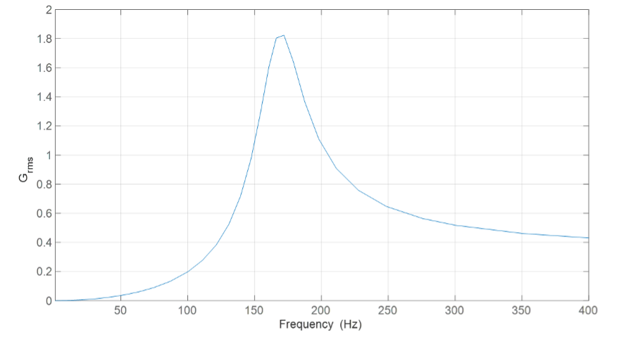
Figure 4: Vibration performance of the LRA under changing driving frequency.
Linear Resonant Actuators represent a refined balance between mechanical and electromagnetic design, allowing precise control of vibration response for compact electronic systems. By understanding the relationship between mass, spring stiffness, damping, and electromagnetic force, engineers can optimize LRAs for higher efficiency, faster response, and improved tactile feedback. Though simplified, the linear model offers valuable insights into system behavior and serves as a foundation for more advanced simulations and product development.
At Quadrant, we continuously explore the science behind magnetics and motion to support innovation in actuator and vibration technologies.To learn more about our expertise in magnetic systems and precision motion solutions, contact us at [email protected] .